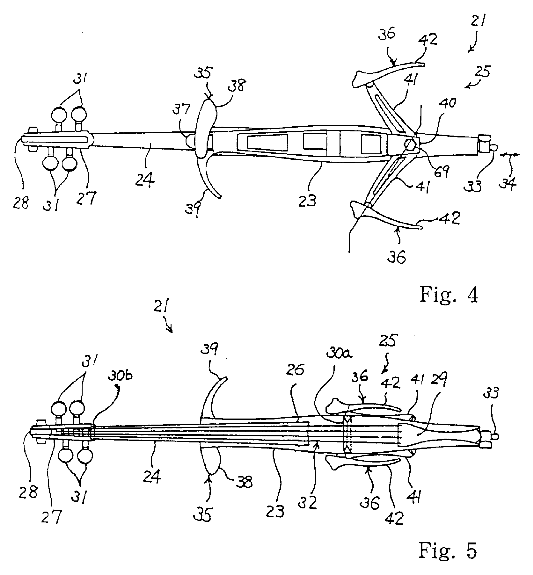
A cello's knee supports swing inward toward its narrow central body. The strings keep their length while the width needed during playing folds away. With a narrow central body, the places where a player holds the instrument still have a job to do.
Yamaha's drawings also send a guitar's outline around its back and add small branches to wind-instrument tubes. Storage space is one constraint. The positions of knees and fingers, the resonance of air and the movement of striking parts set others.
Bring the cello's knee supports back toward its body
What is it?
Arms extend to either side of a slim body, carrying pads that the player holds between their knees. For storage, the arms turn along the body and the pads change angle to nest closer to it.
The arm pivots are tilted relative to the back of the body, setting the path along which the supports fold. Clamps and locks secure the playing position. The chest support is a separate component.
- ASSIGNEE
- Yamaha Corporation
- PRIORITY
- 1999-03-03
- PUBLISHED
- 2001-07-03
- PUBLICATION
- US6255565B1
- INVENTORS
- Shinya Tamura
Swing the guitar's outline behind the strings
What is it?
Two frames provide the outline around a central string-bearing body. One frame pivots about the body's lengthwise direction, passing around the rear until it approaches the frame on the other side.
The dashed and solid positions in FIG. 3 show how the frame moves without crossing the strings. FIG. 4 shows the connecting screw passing through the frame end and serving as its pivot axis.
- ASSIGNEE
- Yamaha Corporation
- PRIORITY
- 2012-10-29
- PUBLISHED
- 2014-05-01
- PUBLICATION
- US20140116226A1
- INVENTORS
- Konyo Saito / Hiroyuki Tsuruhashi
Give a drum kit one place to fold into
What is it?
Arms carry seven playing surfaces in front of, behind and above a central board. For storage, the arms and pads turn toward the board, bringing the pads within its outer outline.
The large rectangle remains visible in the deployed view shown here. It provides a common support; the publication's storage view shows the circular pads packed against that same area.
- ASSIGNEE
- Yamaha Corporation
- PRIORITY
- 2006-03-23
- PUBLISHED
- 2011-02-17
- PUBLICATION
- US20110036230A1
- INVENTORS
- Marianne Bailey
Slip a different weight onto the beater from the side
What is it?
A movable retainer sits just below the part that strikes the bass drum. Pulling it down against a spring opens a gap for a weight, which is then held between the retainer and the beater head.
A slot in the weight admits the rod from the side. The weight can be inserted near the striking head without taking the head off or threading the weight along the entire rod.
- ASSIGNEE
- Yamaha Corporation
- PRIORITY
- 2015-09-30
- PUBLISHED
- 2017-06-20
- PUBLICATION
- US9685146B2
- INVENTORS
- Fumihiro Shigenaga / Shinsuke Irisa
Add a short branch to a straight tube
What is it?
A short auxiliary tube joins the main pipe near the blowing section. Choosing its length and cross-sectional area is intended to approximate the resonance of a tapered pipe while retaining constant-width main and branch tubes.
In FIG. 6B the junction sits outside the mouthpiece. The description separates the branch from the mouthpiece attachment so that a conventional saxophone mouthpiece can be fitted and removed.
- ASSIGNEE
- Yamaha Corporation
- PRIORITY
- 2010-02-12
- PUBLISHED
- 2011-08-18
- PUBLICATION
- US20110197737A1
- INVENTORS
- Hideyuki Masuda / Yuichiro Suenaga
Put a branching air passage inside the mute
What is it?
The proposed bell-mounted mute contains a main pipe and a narrower auxiliary pipe. The auxiliary passage branches from the main pipe, bends back to run alongside it and opens at its far end.
The publication describes choosing tube dimensions and junction position to approximate the bell's resonance while reducing sound through a less flared outlet. The drawing shows the passage layout, not measured attenuation or playing feel.
- ASSIGNEE
- Yamaha Corporation (assignment record; cover: YAMAMHA CORPORATION)
- PRIORITY
- 2011-08-10
- PUBLISHED
- 2013-02-14
- PUBLICATION
- US20130036895A1
- INVENTORS
- Hideyuki Masuda / Yuichiro Suenaga
Release the driving action before stopping the hammer
What is it?
In silent mode, a stopper enters the path of the hammer shanks and catches them before the hammers strike the strings. At the same time, the jack that pushes the hammer is made to escape earlier.
The stopper is split between the bass and the middle-to-high registers. One motor drives two transmission paths that switch both stopper sections and the timing changer together.
- ASSIGNEE
- Yamaha Corporation (assignment recorded 2002-10-08)
- PRIORITY
- 2001-12-13
- PUBLISHED
- 2003-06-19
- PUBLICATION
- US20030110897A1
- INVENTORS
- Katsuo Itou
Adjust the shaft that carries vibration into the soundboard
What is it?
Current in a coil produces motion that a shaft carries into the soundboard. FIG. 3 shows the installation within the piano; FIG. 4 shows the actuator and its projecting connection.
A threaded shaft adjusts the distance to the soundboard during mounting. The connection can reach the board while the voice coil remains in its intended position within the magnetic circuit.
- ASSIGNEE
- Yamaha Corporation
- PRIORITY
- 2011-12-15
- PUBLISHED
- 2015-05-14
- PUBLICATION
- US20150128790A1
- INVENTORS
- Kenta Ohnishi / Yuji Takahashi
AFTER THE FIGURES
Keeping the connections that make playing possible
The cello and guitar preserve a supporting outline during performance, then rearrange it for transport. The wind-instrument designs use branch tubes to reshape acoustic behavior. Changing an instrument's outline means deciding again which part should perform each function.
The two piano proposals make that choice especially clear. One stops the hammer before it reaches the strings; the other sends vibration to the soundboard from a different source. Alongside the visible shape, there is another structure to follow, the path from the player's body to the sound.
SOURCES
Primary sources
- US6255565B1 — Electric stringed musical instrument having stretchable frame body
- US20140116226A1 — Electric stringed instrument
- US20110036230A1 — Percussion instrument and electronic percussion instrument
- US9685146B2 — Drum beater and drum foot pedal apparatus
- US20110197737A1 — Pipe structure of wind instrument
- US20130036895A1 — Mute for brass instrument
- US20030110897A1 — Silent system with split hammer stopper and keyboard musical instrument having the same
- US20150128790A1 — Actuator for vibrating a sound board in a musical instrument and method for attaching same