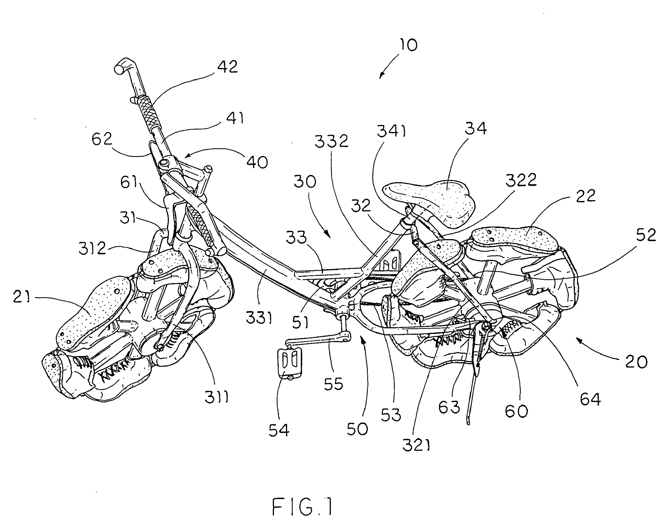
Shoes line the outside of the wheels. Each turn of the hub brings another foot to the ground. A familiar bicycle silhouette begins to change at its point of contact with the road.
Change the rider’s motion, the surface beneath the vehicle or the way it packs away, and cycles acquire oar-like controls, skis or telescoping structures. Following the links in these drawings reveals where each task has moved.
A wheel that takes one step at a time
What is it?
Those shapes around the wheels are shoes. Radial legs carry foot-shaped parts through ankle joints, bringing each foot to the ground as the hub turns.
Springs at the ankle control the orientation before and after contact. The application describes a heel-to-toe motion and even discusses replacing the shoes.
- ASSIGNEE
- Individual
- PRIORITY
- 2003-12-01
- PUBLISHED
- 2005-06-02
- PUBLICATION
- US20050116539A1
- INVENTORS
- Jiazheng Lu
Storing a jump inside the frame
What is it?
Nested frames contain members that store energy when compressed or stretched. A wheel-mounted pin engages a hook, using wheel rotation, a cable and gears to load both sets of members.
When the hook releases, the stored energy moves the frames in opposite directions, intended to produce a jump. The description includes spring and piston embodiments.
- ASSIGNEE
- Individual
- PRIORITY
- 1992-07-23
- PUBLISHED
- 1994-04-12
- PUBLICATION
- US5301969A
- INVENTORS
- Wayne Bynoe
Push and pull both drive the rear wheel
What is it?
The rider sits low with legs extended and moves the control unit back and forth like an oar. A dual-motion gear connects both the push and pull strokes to rear-wheel drive.
Tilting the same unit left or right steers. The wheels overlap in this side view: the illustrated embodiment has two front wheels and one rear wheel.
- ASSIGNEE
- Taz's Custom Welding, Inc.; Douglas R. Montez
- PRIORITY
- 2004-08-19
- PUBLISHED
- 2007-07-03
- PUBLICATION
- US7237786B2
- INVENTORS
- Douglas R. Montez
Giving the feet an elliptical path
What is it?
Long links carry the foot platforms. One end travels along a guide track while the other rotates with a crank, combining those motions into an elliptical path that supplies the drive.
The crank sits high at the rear of the frame, while the guides extend along the lower frame. The mechanism that determines the footpath also shapes the vehicle.
- ASSIGNEE
- PT Motion Works Inc
- PRIORITY
- 2006-11-21
- PUBLISHED
- 2010-05-18
- PUBLICATION
- US7717446B2
- INVENTORS
- Bryan Pate / Brent Teal
Lower the floats and pedal a propeller
What is it?
Pontoons pivot from positions above the wheels for land travel to lowered positions for flotation. The rear view compares the deployed floats with dotted outlines of their stowed positions.
For water travel, a detachable shaft-and-gear assembly transfers pedal rotation to a propeller behind the frame. The patent also describes transmitting handlebar movement to aquatic steering.
- ASSIGNEE
- Individual
- PRIORITY
- 1971-06-25
- PUBLISHED
- 1974-10-29
- PUBLICATION
- US3844246A
- INVENTORS
- Benjamin Carter Locher
A ski in front, a pedal-driven track behind
What is it?
A steerable ski replaces the front wheel, and a belt track wraps around two wheels at the rear. Pedals and a chain turn a drive wheel inside the track.
The description also provides a spring-loaded mechanism to maintain belt tension. A long contact surface requires hardware to keep it in shape as it circulates.
- ASSIGNEE
- The Raymond Lee Organ. Inc. (part interest)
- PRIORITY
- 1974-08-13
- PUBLISHED
- 1975-10-28
- PUBLICATION
- US3915468A
- INVENTORS
- Reynald L. Hoareau
Packing the spokes into a narrow bundle
What is it?
A folded frame still leaves full-size wheels to carry. This design uses an extendable hub and spokes, together with separate rim portions, to reduce the wheel assembly itself.
Separating the hub ends lets the spokes fold toward its axis. The hub and spokes then shorten into the illustrated bundle. The removed rim portions are not shown here.
- ASSIGNEE
- National Tsing Hua University
- PRIORITY
- 2010-08-03
- PUBLISHED
- 2012-02-09
- PUBLICATION
- US20120032497A1
- INVENTORS
- Dongliang Daniel Sheu / Shang-Ji Lee
Using the empty wheel as storage space
What is it?
This design keeps its wheels round. After the spokeless wheels are removed, folding the saddle post operates links and gears that draw the frame members and fork together.
The sequence leaves large rings beside a progressively smaller frame. The description proposes placing the folded frame within the open centers of the wheels and carrying the assembly in a fitted bag.
- ASSIGNEE
- Individual
- PRIORITY
- 2010-03-05
- PUBLISHED
- 2012-12-20
- PUBLICATION
- US20120319377A1
- INVENTORS
- Gianluca Sada
AFTER THE FIGURES
Where the force goes changes the ride
Walking wheels and a snow track change the contact with the surface. Rowing controls and an elliptical linkage change the human input. The amphibious design redirects that input to a propeller.
Storage presents another choice: shrink the wheel’s structure or use its open center. Across the eight designs, the familiar vehicle becomes a set of relationships between the body, transmission, contact surface and space to carry it.
SOURCES
Primary sources
- US20050116539A1 — Walking wheel for bicycle
- US5301969A — Bicycle with jumping capability
- US7237786B2 — Rowing bicycle
- US7717446B2 — Self-propelled vehicle propelled by an elliptical drive train
- US3844246A — Amphibious bicycle
- US3915468A — Snow bike
- US20120032497A1 — Foldable Wheel
- US20120319377A1 — Foldable bicycle with spokeless wheels