The umbrella can look like a solved object: hold the handle, open the ribs, and let the canopy stop rain or sun. In patent drawings, inventors repeatedly challenge familiar assumptions, starting with the need to hold the umbrella by hand. The canopy flies on a drone, attaches to the body, or rides on a backpack.
Then the user changes too. One umbrella covers a dog; another becomes part of a wheelchair. Others measure the rain they are blocking, display a forecast before the rain begins, turn the ribs into lights, or surround a patio with cooling mist. At the far end, a small wind-driven rotor generates electricity for the umbrella itself.
The ten patents below are US publications. From Patents did not find public evidence tying any of these ten patents one-to-one to a specific commercial product, so every Patent → Product status remains unconfirmed.
Let the umbrella follow you by drone
What is it?
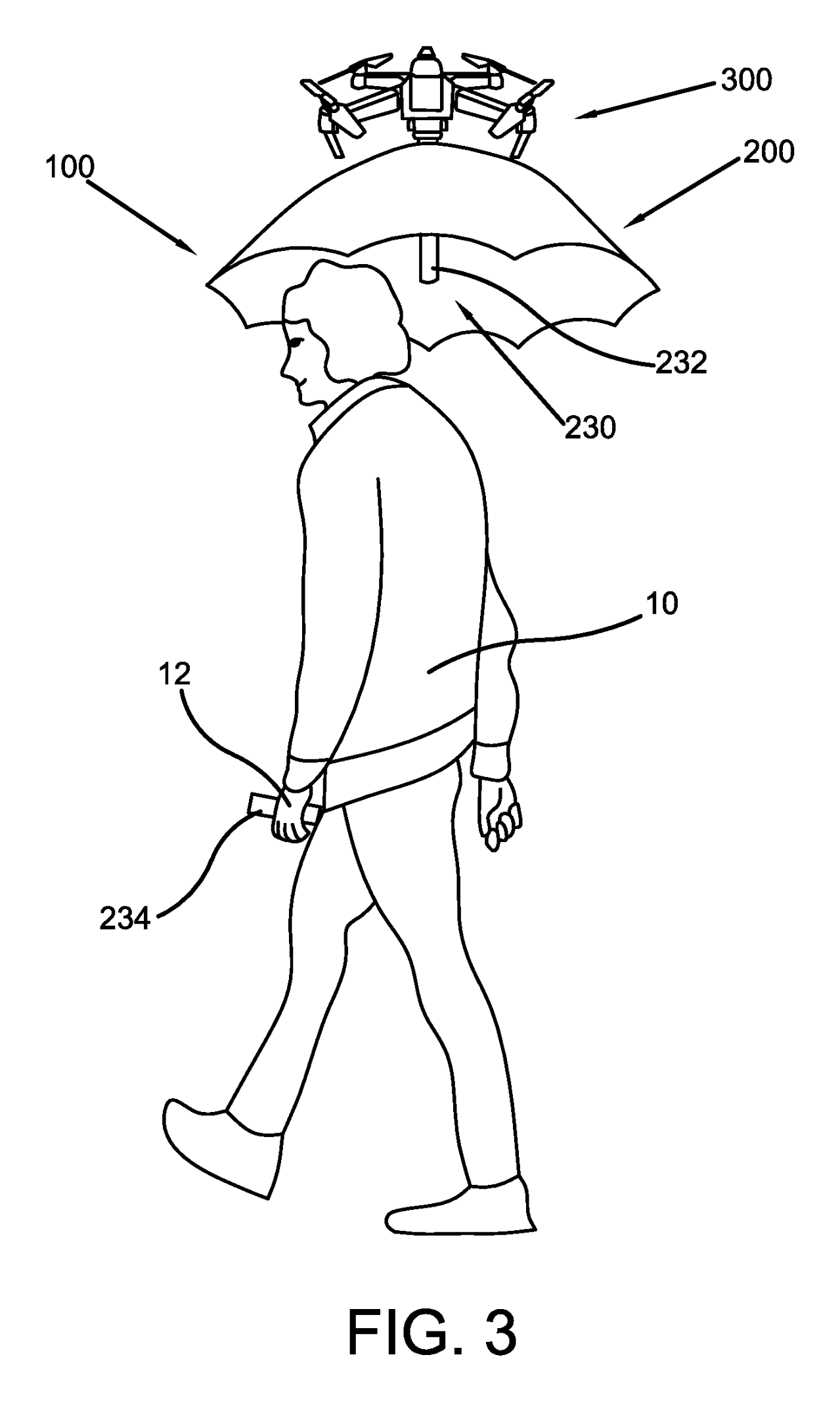
This invention attaches at least one drone to an umbrella so the canopy can hover over the user without being held. FIG. 3 puts the person and the flying umbrella in the same scene, making the basic idea immediately legible.
The detachable handle can carry a GPS transmitter that communicates with the drone. Instead of the person carrying the umbrella along, the umbrella follows the person.
- ASSIGNEE
- Individual
- PRIORITY
- 2021-04-27
- PUBLISHED
- 2022-10-27
- PUBLICATION
- US20220340276A1
- INVENTORS
- Joseph Harris
Wear the umbrella on your shoulders and waist
What is it?
“Wearable umbrella” uses a flexible support and body attachment so the user does not need to keep one hand on a handle. FIG. 1 shows the canopy and the shoulder-and-torso support as one wearable structure.
The goal is similar to the drone umbrella, but the solution is the opposite: nothing flies. The umbrella moves toward clothing and wearable equipment instead.
- ASSIGNEE
- Individual
- PRIORITY
- 2022-04-18
- PUBLISHED
- 2025-02-06
- PUBLICATION
- US20250040671A1
- INVENTORS
- Abdullatif ALSUBAIE / Youssif ALSUBAIE
Make the backpack hold an ordinary umbrella
What is it?
This patent builds umbrella supports into a backpack assembly. FIG. 3 shows a conventional-looking canopy held over the wearer by a structure connected to the pack.
Instead of redesigning the umbrella itself, the invention replaces the job normally performed by the user's hand. The same backpack can also be configured with a child carrier.
- ASSIGNEE
- Individual
- PRIORITY
- 2002-08-15
- PUBLISHED
- 2004-02-19
- PUBLICATION
- US20040031827A1
- INVENTORS
- Robert Haber
Give the dog its own umbrella on the leash
What is it?
This invention combines a pet umbrella and leash into one structure. The convex side of the canopy faces the handle, while the leash attaches on the opposite side so the cover can remain above the animal.
FIG. 2 shows the result directly: a dog walking through rain beneath a canopy while the owner controls both pet and umbrella through the same assembly.
- ASSIGNEE
- Individual
- PRIORITY
- 2003-02-24
- PUBLISHED
- 2004-10-14
- PUBLICATION
- US20040200437A1
- INVENTORS
- Irina Zhadan-Milligan / Yuri Zhadan
Deploy the umbrella out of a wheelchair
What is it?
This patent integrates an umbrella assembly with a wheelchair. The canopy and elongated ribs can be stored in a housing and driven outward into an open position.
FIG. 8 shows the relationship between the mobility device and the umbrella assembly, going beyond a simple clamp that merely holds a normal umbrella.
- ASSIGNEE
- Ellen D. Fitzgerald
- PRIORITY
- 2014-02-28
- PUBLISHED
- 2017-04-13
- PUBLICATION
- US20170099917A1
- INVENTORS
- Ellen D. Fitzgerald / Jeffrey R. Lake
Measure the rain with the umbrella that is blocking it
What is it?
“Umbrella with rain measuring device” places a collector cup at the top of the umbrella and routes rainwater through a hollow shaft to a measuring receptacle.
A normal umbrella simply sheds water. This one intentionally gathers the water it encounters and turns rainfall into a measurement.
- ASSIGNEE
- Individual
- PRIORITY
- 2006-02-01
- PUBLISHED
- 2007-11-01
- PUBLICATION
- US20070251556A1
- INVENTORS
- Irwin Porter
Ask the umbrella about the weather before opening it
What is it?
This invention puts a weather-forecast display into the umbrella itself. FIG. 4 shows interface elements in the handle, including a small screen for precipitation and temperature information.
The object used after rain starts now participates in the earlier decision of whether it will be useful at all.
- ASSIGNEE
- Ambient Devices Inc
- PRIORITY
- 2001-09-19
- PUBLISHED
- 2007-11-08
- PUBLICATION
- US20070256716A1
- INVENTORS
- Benjamin Resner / Pritesh Gandhi / Nicholas Negroponte / Robert Dredge / David Rose
Turn the umbrella ribs into a light display
What is it?
“Personal lighted umbrella” places light sources such as LEDs on flexible strips and controls properties including color, intensity, and pulsing patterns. FIG. 3 shows the umbrella as a broad illuminated surface.
The lighting can improve visibility, but the patent also describes controlled patterns and interaction with external signals. The canopy becomes more than passive fabric.
- ASSIGNEE
- Nuytkens Industries LLC
- PRIORITY
- 2020-12-10
- PUBLISHED
- 2022-06-16
- PUBLICATION
- US20220183429A1
- INVENTORS
- Margaret H. Nuytkens / Peter R. Nuytkens / Amy R. Nuytkens / Mark H. Nuytkens
Drop a curtain of cooling mist around the shade
What is it?
This patio umbrella runs tubing and nozzles around the perimeter to create a curtain of mist. FIG. 1 shows two people seated within the ring of spray.
The mist is directed downward and slightly outward so the goal is to cool the covered area while keeping the occupants comparatively dry. The umbrella begins managing the air around its boundary.
- ASSIGNEE
- Individual
- PRIORITY
- 2004-02-06
- PUBLISHED
- 2005-08-11
- PUBLICATION
- US20050172987A1
- INVENTORS
- Terrence Byrnes
Harvest the wind above the umbrella and feed the power back
What is it?
This hands-free automatic umbrella combines a body-mounted storage case, powered opening and closing, lighting, and a rotating device at the canopy peak. FIG. 4 shows the open umbrella with the rotor and light elements.
The patent describes using electricity generated from wind to power components such as lights and motors. Wind, normally one of the umbrella's enemies, becomes part of its power source.
- ASSIGNEE
- Individual
- PRIORITY
- 2020-11-04
- PUBLISHED
- 2022-05-05
- PUBLICATION
- US20220133005A1
- INVENTORS
- Roya Songhorian
AFTER THE FIGURES
The more jobs the umbrella gets, the less it resembles a roof you hold
The first inventions mostly change who or what supports the canopy: a drone, the wearer's body, a backpack, or a wheelchair. Moving that one job away from the hand is enough to make the umbrella feel closer to a robot, wearable, or mobility accessory.
The middle of the set turns the umbrella into an information device. It measures rain, reports weather that has not arrived yet, and lights up after dark. Add mist and the object starts controlling the air around the shaded space rather than merely blocking what falls from above.
By the time a rotor is generating electricity from wind, bad weather is no longer only something the umbrella resists. It also becomes an input. A seemingly finished object still has room to change when its jobs are separated into holding, sheltering, measuring, informing, cooling, and powering.
SOURCES
Primary sources
- US20220340276A1 — Drone Umbrella Device
- US20250040671A1 — Wearable umbrella
- US20040031827A1 — Backpack for carrying an umbrella and/or child hands free
- US20040200437A1 — Pet umbrella and combined pet leash and umbrella
- US20170099917A1 — Wheelchair having an umbrella assembly
- US20070251556A1 — Umbrella with rain measuring device
- US20070256716A1 — Weather forecasting umbrella
- US20220183429A1 — Personal lighted umbrella
- US20050172987A1 — Umbrella with cooling misting screen
- US20220133005A1 — Hands-free, automatic umbrella with lighting mechanism and rotating device for electricity generation from wind