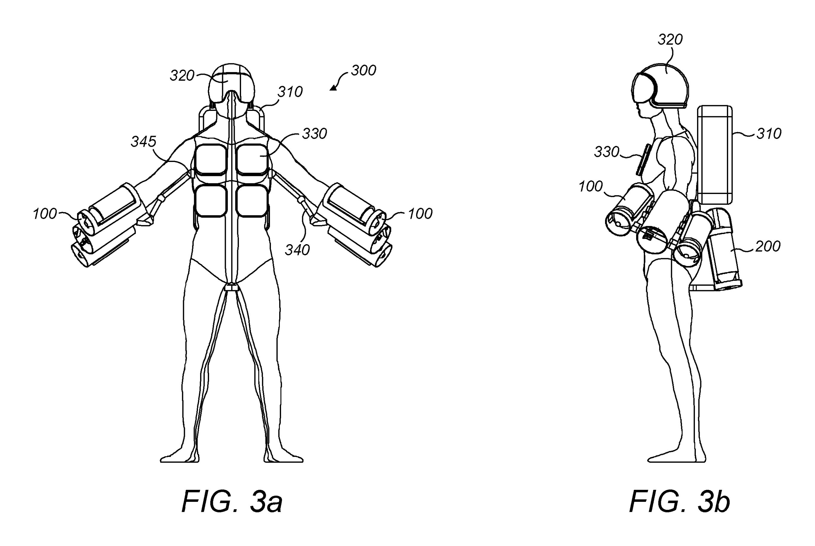
A jet suit uses the wearer’s arms to steer thrust. Elsewhere, a flying frame picks up a passenger pod, and two aircraft connect at their wingtips. Each proposal rearranges the relationship between the person, the propulsion system and the airframe.
Wear jets on your arms and back instead of boarding an airplane
What is it?
The proposed flight system places jet propulsion units on the user’s back and arms. Moving the arms changes the direction of thrust.
- ASSIGNEE
- Gravity Industries Ltd.
- PRIORITY
- 2017-02-22
- PUBLISHED
- 2019-12-19
- PUBLICATION
- US20190382114A1
- INVENTORS
- Richard Browning
Use pedal power to flap enormous wings like a bird
What is it?
"Man-powered ornithopter-sailplane" describes an aircraft that uses human power to move large wings in a bird-like flapping cycle. FIG. 1 places the pilot at the center of a long structure with broad wings extending to both sides.
Most human-powered aircraft favor a fixed wing and propeller because human output is limited. This proposal instead spends that scarce power on moving the wings themselves, returning to one of the oldest intuitions about flight.
- ASSIGNEE
- Individual
- PRIORITY
- 2003-09-11
- PUBLISHED
- 2007-02-08
- PUBLICATION
- US20070029441A1
- INVENTORS
- Remigijus Dainys
Put four huge ducted fans at the corners of the vehicle
What is it?
The proposed personal aircraft arranges four ducted fans around the cockpit, with the side fans able to change direction.
- ASSIGNEE
- Bell Helicopter Textron Inc.
- PRIORITY
- 2017-06-14
- PUBLISHED
- 2018-12-20
- PUBLICATION
- US20180362160A1
- INVENTORS
- Kirk L. Groninga / John Lloyd / Daniel B. Robertson
Send a flight frame to pick up a detachable passenger pod
What is it?
The flight frame and passenger pod are separate assemblies. The frame approaches a pod on the ground and attaches to it for transport.
- ASSIGNEE
- Bell Helicopter Textron Inc.
- PRIORITY
- 2016-07-01
- PUBLISHED
- 2018-05-08
- PUBLICATION
- US9963228B2
- INVENTORS
- John Richard McCullough / Paul K. Oldroyd
Dock two aircraft together wingtip-to-wingtip in flight
What is it?
The proposed docking mechanism connects aircraft at their wingtips during flight.
- ASSIGNEE
- Aurora Flight Sciences Corp. (original assignee)
- PRIORITY
- 2007-09-14
- PUBLISHED
- 2011-11-22
- PUBLICATION
- US8061646B2
- INVENTORS
- Martin L. Gomez / Robert Parks / Adam J. Woodworth
Hide wings and propellers inside a body that looks like a drink bottle
What is it?
The proposed aircraft deploys wings, a tail and a propeller from a body shaped like a drinks bottle.
- ASSIGNEE
- University of Florida Research Foundation, Inc.
- PRIORITY
- 2008-08-25
- PUBLISHED
- 2014-11-18
- PUBLICATION
- US8888035B2
- INVENTORS
- Richard Charles Lind Jr. / Daniel Thurmond Grant / David Eaton
Fire stored telescoping wings outward with gas
What is it?
The proposed wing uses gas pressure to push nested sections outward rapidly, then locks them in the extended position.
- ASSIGNEE
- The Boeing Company (assignment recorded)
- PRIORITY
- 2006-06-09
- PUBLISHED
- 2009-08-20
- PUBLICATION
- US20090206193A1
- INVENTORS
- David J. File
Arrange feather-like panels so the wing itself can morph
What is it?
The proposed wing uses linked feather-like panels whose spread and overlap change the shape of the wing.
- ASSIGNEE
- Japan Aerospace Exploration Agency (JAXA)
- PRIORITY
- 2019-08-27
- PUBLISHED
- 2022-09-08
- PUBLICATION
- US20220281585A1
- INVENTORS
- Daichi Wada
Make the wing a giant ring and distribute propellers around it
What is it?
This distributed-propulsion proposal includes an aircraft with multiple propellers arranged around a closed ring-shaped wing.
- ASSIGNEE
- Textron Innovations Inc.
- PRIORITY
- 2016-05-13
- PUBLISHED
- 2023-03-14
- PUBLICATION
- US11603203B2
- INVENTORS
- Carlos Alexander Fenny / Rohn Lee Olson
Put the passenger in a 'cocoon' and fly the whole capsule vertically
What is it?
The proposed vehicle surrounds the passenger with a cocoon-shaped capsule and places propulsion units outside it for vertical flight.
- ASSIGNEE
- Individual
- PRIORITY
- 2019-07-03
- PUBLISHED
- 2022-11-10
- PUBLICATION
- US20220355922A1
- INVENTORS
- Alberto Carlos Pereira Filho
AFTER THE FIGURES
What these ten figures reveal
These ten proposals separate and recombine the familiar parts of an aircraft. Propulsion moves onto the body, passenger pods detach from flight frames, and separate aircraft can join at their wingtips.
Wing design ranges from telescoping sections and feather-like panels to a closed ring lined with propellers. Flight becomes a question of how the body, cabin, wings and propulsion fit together.
SOURCES
Primary sources
- US20190382114A1 — A flight system
- US20070029441A1 — Man-powered ornithopter-sailplane
- US20180362160A1 — Personal air vehicle with ducted fans
- US9963228B2 — Aircraft with selectively attachable passenger pod assembly
- US8061646B2 — Wing tip docking system for aircraft
- US8888035B2 — Morphing aircraft
- US20090206193A1 — Ballistically deployed telescoping aircraft wing
- US20220281585A1 — Morphing wing, flight control device, flight control method, and storage medium
- US11603203B2 — Distributed propulsion system
- US20220355922A1 — Vertical take-off and landing cocoon-type flying vehicle