Snap is easy to associate with the phone camera and AR lenses. Across its patent drawings, though, a different pattern appears: the interface keeps extending beyond the phone screen. A wristwatch becomes an anchor for a launcher. Fingers become controls. Two people use their own hands to align the coordinates of a shared AR scene.
The idea then spreads into the room. Eyewear can trigger projectors and other connected devices. Spatial audio can guide a person toward a target. Clothing can be replaced virtually before it is worn. Hidden people can be overlaid beyond a barrier, small work can be magnified in place, and the display itself can move all the way to the surface of the eye.
These ten proposals appear in Snap US patent publications. From Patents has not confirmed one-to-one implementation in specific commercial Snap products.
Turn a wristwatch into an AR launcher
What is it?
This patent anchors an AR eyewear interface to the position of a wristwatch. FIG. 15 shows a user looking at the watch while a three-dimensional launcher with items such as a camera and a car appears around it.
Instead of placing a menu at an arbitrary point in midair, the system uses a physical object the user already knows how to present and look at. Raising the wrist becomes the gesture that brings the interface into view.
- ASSIGNEE
- Snap Inc.
- PRIORITY
- 2017-08-25
- PUBLISHED
- 2021-12-23
- PUBLICATION
- US20210397000A1
- INVENTORS
- Jonathan M. Rodriguez II
Control what you see with a finger gesture
What is it?
“Gesture control on an eyewear device” uses the wearer’s hand as an input source for virtual content. FIG. 7 presents the relationship between the displayed content and a hand gesture within the eyewear experience.
A separate handheld controller is not required. The position and motion of the fingers themselves can become the command, bringing the act of “touching the UI” into space.
- ASSIGNEE
- Snap Inc.
- PRIORITY
- 2020-12-22
- PUBLISHED
- 2022-06-23
- PUBLICATION
- US20220197393A1
- INVENTORS
- Kyle Goodrich / Andrew James McPhee / Daniel Moreno
Touch fingertips to align two people's AR worlds
What is it?
Shared AR requires two devices to agree on where the same place is. This patent uses the users’ own hands as common reference points that both eyewear devices can observe.
FIGS. 5B–5C show two people facing each other and touching fingertips, with hand joints used to establish the spatial relationship between their separate coordinate systems.
- ASSIGNEE
- Snap Inc.
- PRIORITY
- 2023-02-28
- PUBLISHED
- 2024-08-29
- PUBLICATION
- US20240288946A1
- INVENTORS
- Georgios Evangelidis / Bernhard Jung / Ilteris Kaan Canberk / Daniel Wolf / Balázs Töth / Márton Gergely Kajtár / Branislav Micusik
Use a phone like a brush for painting in 3D
What is it?
This patent treats a physical device such as a phone as a virtual paintbrush. The eyewear tracks its position and orientation and uses that motion to generate lines or shapes in three-dimensional space.
FIG. 8A shows a box-like 3D form with differently colored edges inside the viewing area. The drawing surface is no longer the glass of the phone; it is the space in front of the user.
- ASSIGNEE
- Snap Inc.
- PRIORITY
- 2020-06-30
- PUBLISHED
- 2024-06-27
- PUBLICATION
- US20240211057A1
- INVENTORS
- Ilteris Canberk / Daniel Moreno
Walk into a room and let the physical devices respond
What is it?
“Augmented reality with eyewear triggered IoT” connects the wearer’s location and pose to devices in the environment. FIG. 9B shows a user facing a projected sun-like image while AR elements are aligned with the physical projection.
The patent also describes examples such as changing a projector’s output with head pose or steering a directional fan. The experience is not confined to pixels inside the eyewear; the room itself can produce part of the output.
- ASSIGNEE
- Snap Inc.
- PRIORITY
- 2020-03-31
- PUBLISHED
- 2024-02-08
- PUBLICATION
- US20240045494A1
- INVENTORS
- Ilteris Canberk / Shin Hwun Kang / Doug Mead
Guide someone with the direction of a sound
What is it?
This patent identifies a target location in the surrounding environment and generates spatial audio that appears to come from that direction. FIGS. 6A–6B map the wearer and several targets within a room.
The system does not need to keep an arrow permanently in front of the eyes. Direction itself can be communicated through hearing, moving part of the interface away from the visual field.
- ASSIGNEE
- Snap Inc.
- PRIORITY
- 2020-03-31
- PUBLISHED
- 2021-08-10
- PUBLICATION
- US11089427B1
- INVENTORS
- Ilteris Canberk / Shin Hwun Kang / James Powderly
Change clothes on the screen before changing them in real life
What is it?
“Virtual clothing try-on” overlays a selected garment on an image or video of a person. FIG. 8 shows a user on a phone screen with clothing choices arranged below the composite view.
Rather than simply browsing product images, the user’s own body becomes the preview surface. The appearance can change digitally before the physical garment does.
- ASSIGNEE
- Snap Inc.
- PRIORITY
- 2020-12-11
- PUBLISHED
- 2024-02-22
- PUBLICATION
- US20240062444A1
- INVENTORS
- Ma'ayan Mishin Shuvi / Avihay Assouline / Itamar Berger
Overlay a person hidden behind a wall
What is it?
“Augmented reality eyewear with x-ray effect” uses information from external cameras or sensors to represent a target that the wearer cannot see directly. FIG. 8A shows users separated by a barrier and the relationship needed to place the hidden information correctly.
The wall is not physically imaged through. Data captured from another viewpoint is aligned with the space so the wearer sees an overlay suggesting what is beyond the obstruction.
- ASSIGNEE
- Snap Inc.
- PRIORITY
- 2021-06-30
- PUBLISHED
- 2025-06-19
- PUBLICATION
- US20250203061A1
- INVENTORS
- Edmund Brown / Benjamin Lucas / Simon Nielsen / Jonathan M. Rodriguez II / Richard Zhuang
Magnify only the tiny work that needs a closer look
What is it?
“Magnified overlays correlated with virtual markers” associates a point in the physical world with a magnified view shown through eyewear. FIG. 8A illustrates the idea in the context of detailed work.
Instead of leaning closer or holding a separate magnifier, the wearer can keep the real object in view while seeing a larger version of the critical area at the same time.
- ASSIGNEE
- Snap Inc.
- PRIORITY
- 2022-07-28
- PUBLISHED
- 2024-02-01
- PUBLICATION
- US20240036336A1
- INVENTORS
- Alexander Sourov / John James Robertson
Put the AR/VR display into the contact lens itself
What is it?
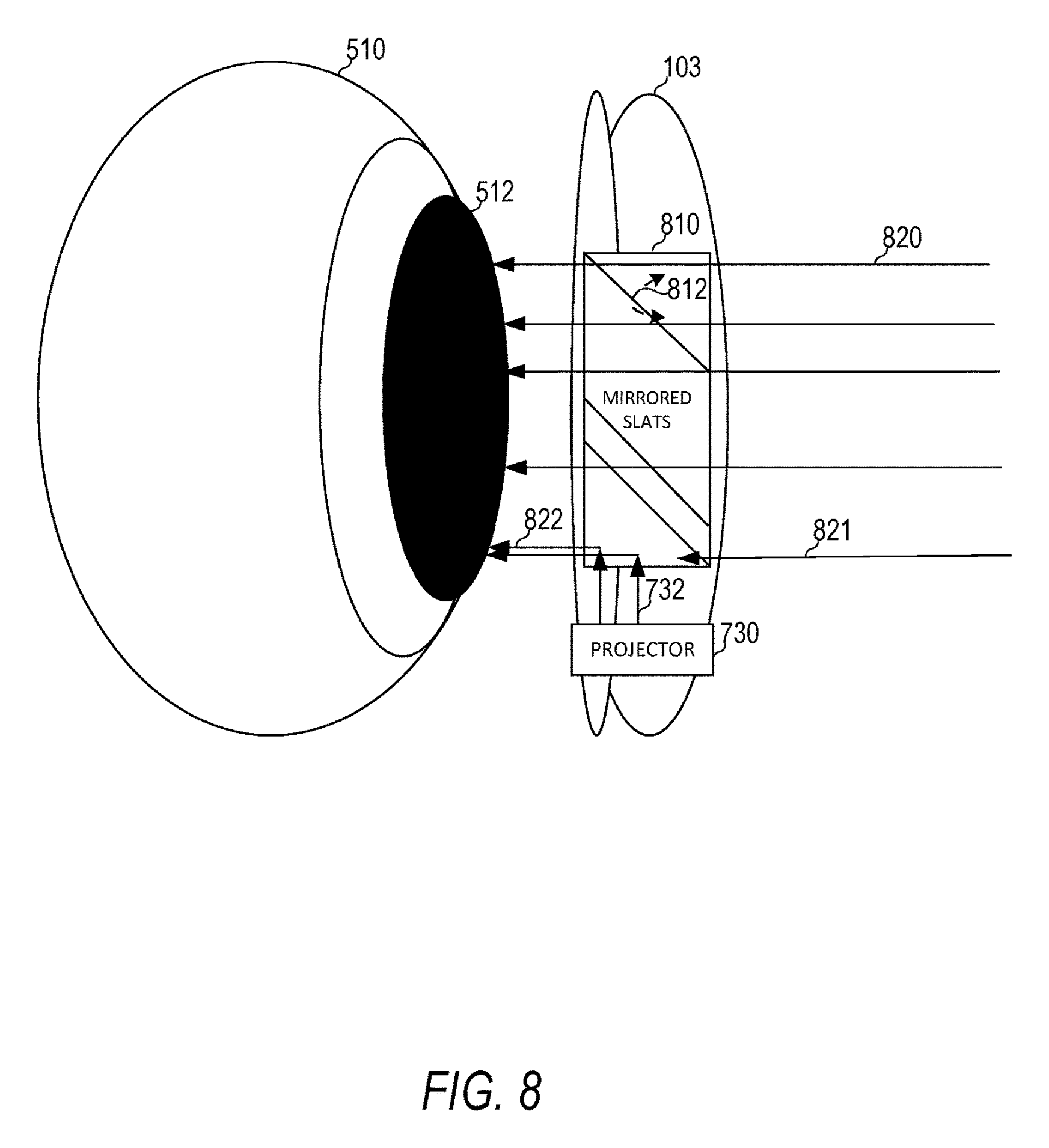
“AR/VR enabled contact lens” describes optical elements and display arrangements inside a contact lens that can support normal viewing, augmented reality and virtual reality modes. FIG. 8 enlarges the eye-and-lens optical relationship.
Eyewear is already a computer placed in front of the face. A contact lens pushes the display still closer until the viewing device and the surface of the eye nearly occupy the same place.
- ASSIGNEE
- Snap Inc.
- PRIORITY
- 2022-04-29
- PUBLISHED
- 2023-11-02
- PUBLICATION
- US20230350203A1
- INVENTORS
- Russell Douglas Patton / Jonathan M. Rodriguez II
AFTER THE FIGURES
As the screen disappears, reality becomes the control surface
In sequence, the center of interaction moves steadily away from the smartphone. First the wrist and fingers take over jobs once performed by a touchscreen. Then other people's hands, room devices and directional sound become parts of the interface. The UI stops being contained by a display and starts attaching itself to bodies and places.
These patents reinterpret reality as something the computer can operate on. A hand can become a calibration marker. A wall can become a surface for hidden information. Clothing and detailed work can be substituted or magnified in place.
By the time the display reaches a contact lens, even the idea of carrying a screen begins to fade. The recurring future in these drawings is a world in which the physical environment itself becomes the interface.
SOURCES
Primary sources
- US20210397000A1 — Wristwatch based interface for augmented reality eyewear
- US20220197393A1 — Gesture control on an eyewear device
- US20240288946A1 — Shared augmented reality eyewear device with hand tracking alignment
- US20240211057A1 — Augmented reality eyewear 3D painting
- US20240045494A1 — Augmented reality with eyewear triggered IoT
- US11089427B1 — Immersive augmented reality experiences using spatial audio
- US20240062444A1 — Virtual clothing try-on
- US20250203061A1 — Augmented reality eyewear with x-ray effect
- US20240036336A1 — Magnified overlays correlated with virtual markers
- US20230350203A1 — AR/VR enabled contact lens