Think of Samsung products and it is easy to picture things with screens: phones, televisions, displays and appliances. In the patent drawings, however, the screen rarely stays inside one rectangle. It moves into a contact lens, jumps from a wearable onto the back of a hand, and bends from a flat slab around the wrist.
The hardware moves too. A wearable robot assists the legs, a round two-wheeled robot shifts its own body to balance, and a landscape display rotates upright and becomes a mirror. Other patents open a device in several directions, make a virtual keyboard follow the palm, or compress sensors and circuitry into a ring.
These ten proposals appear in US patent publications assigned to Samsung Electronics. Some technologies resemble GEMS Hip, Galaxy Z TriFold and Galaxy Ring, but one-to-one implementation of these patents in products remains unverified.
Put a display inside a contact lens
What is it?
"Smart contact lenses for augmented reality" places a display unit inside a contact-lens structure and routes display light toward the wearer's eye. FIG. 16 shows the relationship between the lens and optical path, while FIG. 17 shows the shape of a substrate used for the small display portion.
In ordinary AR glasses, the display and light-routing hardware sit in a frame in front of the face. This proposal pushes those functions into the lens itself. The display is no longer merely behind the glasses; it moves into the object touching the eye.
- ASSIGNEE
- Samsung Electronics Co Ltd
- PRIORITY
- 2014-09-26
- PUBLISHED
- 2016-03-31
- PUBLICATION
- US20160091737A1
- INVENTORS
- Taeho Kim / Sungwoo HWANG / Sangwon Kim / Hoyoung Ahn / Daeyoung Chung
Project a number pad from a wearable onto the back of your hand
What is it?
"Wearable device and control method thereof" combines a body-worn device, camera and projector. The camera detects a target area, and the system can project a virtual UI whose shape or size fits that area. In FIG. 4A, a watch-like device projects a number pad directly onto the back of the hand.
The patent also covers responding to interaction with the projected controls. Instead of making the tiny watch screen physically larger, it temporarily turns nearby skin or another surface into an interface.
- ASSIGNEE
- Samsung Electronics Co Ltd
- PRIORITY
- 2014-11-03
- PUBLISHED
- 2016-05-05
- PUBLICATION
- US20160127624A1
- INVENTORS
- Ji-hwan WOO / Won-Hee Choe
Read leg muscles and add assistance as a step begins
What is it?
"Wearable robot and method for controlling the same" uses an exoskeleton structure worn on the legs together with multiple EMG sensors. The controller looks for a starting point in the walking cycle at which assistance should be applied. FIG. 1 shows the support structure around both legs and sensing points on the lower leg.
The goal is not to drive the legs continuously. Muscle activity is used to infer when the person is starting a step, so the machine can add force at the appropriate moment and follow the user's movement rather than replace it.
- ASSIGNEE
- Samsung Electronics Co Ltd
- PRIORITY
- 2013-11-14
- PUBLISHED
- 2015-05-14
- PUBLICATION
- US20150134080A1
- INVENTORS
- Chang Hyun ROH
Keep a round two-wheeled robot upright by sliding its body
What is it?
"Mobile robot apparatus and control method therefor" proposes a two-wheeled robot in which the main body can move relative to the wheels along an inclined reference axis. FIG. 1 shows the rounded body placed between two large wheels.
A two-wheel machine can lose balance as it accelerates or slows. Here, the body itself becomes an active balancing mass: it moves with or against the direction of travel to help preserve a stable posture.
- ASSIGNEE
- Samsung Electronics Co Ltd
- PRIORITY
- 2021-01-28
- PUBLISHED
- 2023-08-31
- PUBLICATION
- US20230271312A1
- INVENTORS
- Yongtae Kim
Rotate a landscape display upright and let it become a mirror
What is it?
"Electronic apparatus and control method thereof" describes a mirror display that operates in both a normal display state and a mirror state. When the apparatus changes from horizontal to vertical and sensors determine that a user is nearby, it can switch into mirror operation with reference to the user's gaze location.
FIG. 1 makes the idea unusually literal: a landscape screen rotates upright and a person stands in front of it as a mirror. A television and a full-length mirror no longer have to be two separate surfaces.
- ASSIGNEE
- Samsung Electronics Co Ltd
- PRIORITY
- 2023-10-17
- PUBLISHED
- 2025-04-17
- PUBLICATION
- US20250123684A1
- INVENTORS
- Hyeryoung Choi
Roll both sides of a screen into the device
What is it?
"Rollable display device" places rollable driving units on both sides of a flexible screen so it can be unfolded for viewing and rolled inward for storage. FIG. 1 shows a panoramic city image stretched between the two side mechanisms.
A folding display changes shape around fixed crease locations. A rollable one can vary the exposed width more continuously, keeping unused screen inside the housing and pulling out only the area needed at that moment.
- ASSIGNEE
- Samsung Electronics Co Ltd
- PRIORITY
- 2015-05-29
- PUBLISHED
- 2016-12-01
- PUBLICATION
- US20160353588A1
- INVENTORS
- Jinwook Kim / Sangmin Hyun
Open a device in four directions and fold it on multiple axes
What is it?
"Foldable electronic device" describes a display that can fold along two or more axes using several housings and hinge structures. In FIG. 2D, four regions spread from the center in a shape far removed from a conventional two-panel foldable.
The point is not merely to add another fold. Different axes can produce different expanded forms according to the user's choice, giving one device more than a simple closed-versus-open pair of shapes.
- ASSIGNEE
- Samsung Electronics Co Ltd
- PRIORITY
- 2020-12-02
- PUBLISHED
- 2022-10-13
- PUBLICATION
- US20220330438A1
- INVENTORS
- Ivanov IGOR / Seonho HWANG / Hyungsok YEO / Feygenson OLEG / Minwoo YOO / Changryong HEO
Bend a flat screen around your wrist and keep using the same display
What is it?
"Electronic device and method for controlling flexible display" treats bending and wearing state as part of the interface. The device can determine where to show information based on its current shape and the user's situation. FIGS. 14A and 14B show the same flexible object changing from a flat device into something wrapped around the wrist.
Flexibility alone would leave some content hidden on the far side of the arm. By detecting posture and shape, the system can choose a display area that still makes sense in the new form. Physical deformation and UI layout are designed together.
- ASSIGNEE
- Samsung Electronics Co Ltd
- PRIORITY
- 2019-04-19
- PUBLISHED
- 2020-10-22
- PUBLICATION
- US20200335063A1
- INVENTORS
- Jinik KIM / Seongmin Je
Pin a virtual keyboard to the palm of your hand
What is it?
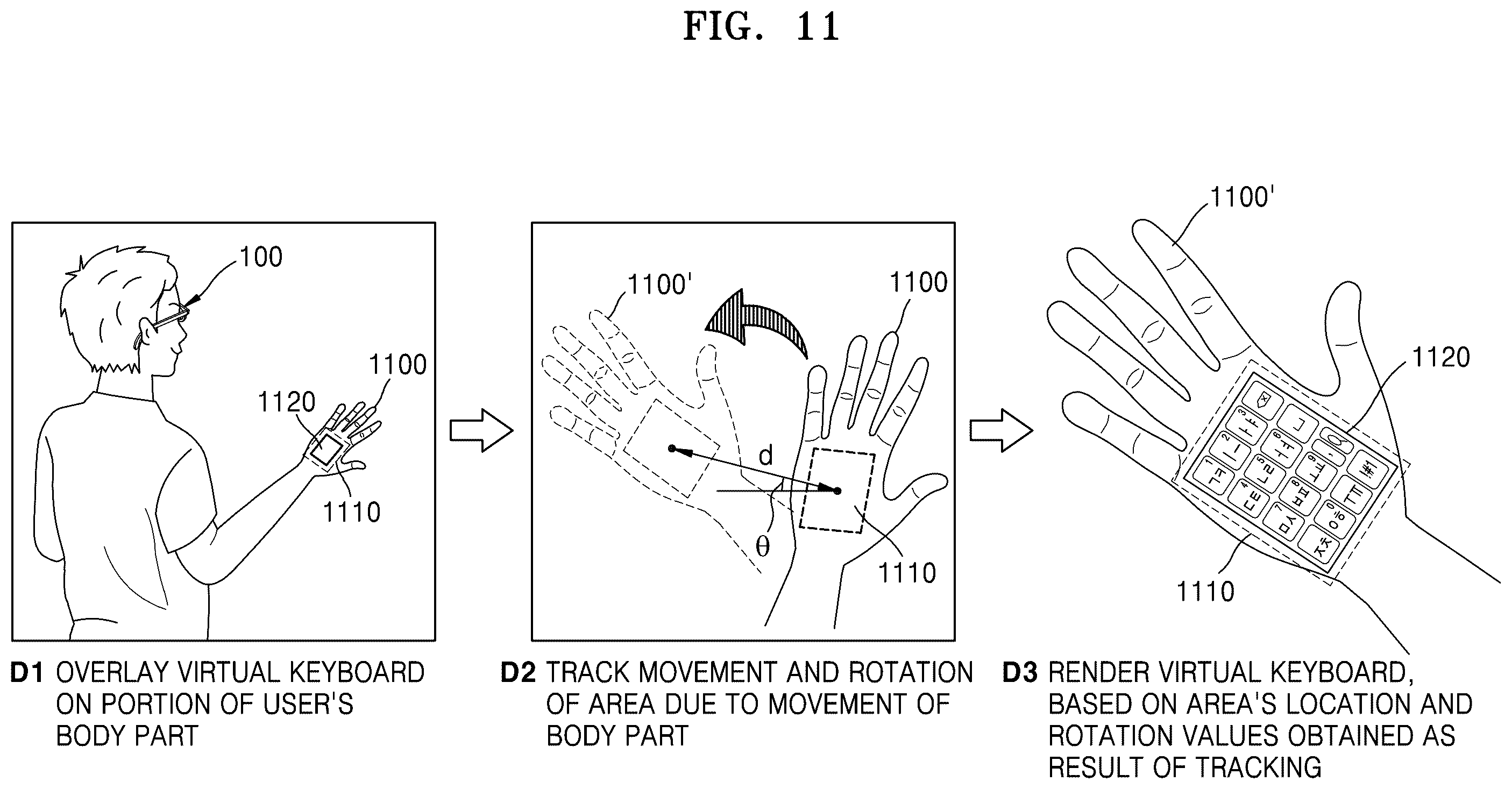
"Augmented reality device capable of displaying virtual keyboard" scans the surrounding real world, detects areas where a virtual keyboard can be overlaid, and renders a suitable keyboard there. FIG. 11 shows a particularly striking case: the keyboard is attached to the user's palm and follows changes in its position and rotation.
If a desk is crowded, there is no reason to insist on one fixed full-size keyboard. The patent can choose a keyboard type using factors such as available shape, size and input language, adapting the input surface to the environment.
- ASSIGNEE
- Samsung Electronics Co Ltd
- PRIORITY
- 2023-09-13
- PUBLISHED
- 2025-05-29
- PUBLICATION
- US20250173026A1
- INVENTORS
- Wonwoo Lee / Jiwon Jeong / Deokho Kim / Gunill KIM
Pack sensors and circuitry into a ring
What is it?
"Ring-type wearable device" uses an outer ring containing the sensor and control units together with a detachable inner ring. FIG. 2 breaks the structure apart to show how those pieces fit inside the wearable.
The patent addresses biological-signal sensing as well as the mundane problem that fingers have many different diameters. Swapping an inner member can adapt the physical fit while helping keep the sensing relationship between skin and electronics more consistent.
- ASSIGNEE
- Samsung Electronics Co Ltd
- PRIORITY
- 2016-02-01
- PUBLISHED
- 2024-05-16
- PUBLICATION
- US20240156218A1
- INVENTORS
- Jin-Hong Min / Jea-Hyuck Lee / Seong-Wook JO / Shin-Hee Cho / Su-Ho LEE
AFTER THE FIGURES
In Samsung patents, the screen keeps losing its fixed address
Across these ten patents, Samsung keeps reopening basic questions: where a screen belongs, what shape a device must keep, and where the boundary between body and machine should sit.
The contact lens pushes information almost to the eye itself. The projector wearable borrows the hand as a temporary keypad. Rollable and multi-axis displays create screen area only when it is needed, while the wrist-wrapped display blurs the distinction between a handheld device and something worn on the body.
Perhaps the most Samsung-like future here is a world in which screens no longer have one address. Lens, hand, mirror, roller, folding housing, ring: the more places that can hold display and sensing functions, the less the future device has to remain one rectangular object.
SOURCES
Primary sources
- US20160091737A1 — Smart contact lenses for augmented reality and methods of manufacturing and operating the same
- US20160127624A1 — Wearable device and control method thereof
- US20150134080A1 — Wearable robot and method for controlling the same
- US20230271312A1 — Mobile robot apparatus and control method therefor
- US20250123684A1 — Electronic apparatus and control method thereof
- US20160353588A1 — Rollable display device
- US20220330438A1 — Foldable electronic device
- US20200335063A1 — Electronic device and method for controlling flexible display
- US20250173026A1 — Augmented reality device capable of displaying virtual keyboard and operation method thereof
- US20240156218A1 — Ring-type wearable device