Nintendo Switch 2's larger display is easy to notice. The decisions that change how it feels are less obvious: a Joy-Con 2 clicks onto the side magnetically, can become a mouse when placed on a surface, and shares a portable console with a new adjustable stand. Each apparently simple action involves several pieces of hardware.
Nintendo publicly identifies US patents associated with Nintendo Switch 2, Joy-Con 2, and the Nintendo Switch 2 Pro Controller through its official virtual patent marking page. An older Nintendo US patent also describes a related game-sharing concept, although its implementation in GameShare is unverified.
Some of these patents claim priority as early as 2015. They should not be mistaken for inventions developed exclusively for the 2025 console. And patent drawings describe protected ideas or examples, not necessarily the exact internal configuration of retail units.
The foundation dates to 2015: a console with detachable sides
What is it?
The first patent was not conceived specifically for Switch 2. US10583356B2 has a 2015 priority date and describes a central display unit with two controllers that can be attached or detached.
What matters is that the controllers can send operation data to the main unit whether or not they are attached. The distinction between a self-contained portable console and a shared, separate-control setup is built into the hardware concept that Switch 2 inherits.
- ASSIGNEE
- Nintendo Co., Ltd.
- PRIORITY
- 2015-06-12
- PUBLISHED
- 2020-03-10
- PUBLICATION
- US10583356B2
- INVENTORS
- Yoshiaki Koizumi / Yui Ehara / Munetaka Nishikawa / Kochi Kawai / Kenichi Mae
The magnetic click is really several mechanisms working together
What is it?
US12691375B2 describes a controller with an elongated projection that fits into the console's side recess, magnetically attractable portions, and an electrical connection. It is more precise than the idea of attaching two objects with a strong magnet.
The recess and projection locate the controller; magnetic force holds it; terminals make an electrical connection. Nintendo's developer interview explains that magnets had been considered for the original Switch, but the connection was not stable enough at the time.
- ASSIGNEE
- Nintendo Co., Ltd.
- PRIORITY
- 2023-08-01
- PUBLISHED
- 2026-03-05
- PUBLICATION
- US20260061307A1
- INVENTORS
- Kazuhiko Koriyama / Shinji Hirose / Kazuki Ebihara
Turn it sideways and the attachment face becomes a mouse
What is it?
The same US12691375B2 also specifies a cavity and opening for a mouse sensor, located among features on the controller's attachment side. The interesting shift is functional: a face designed to connect to the console also becomes part of a pointing device.
Nintendo states that either Joy-Con 2 can function as a mouse in supported games by placing its console-facing side down and sliding it across a suitable surface. Patent claims describe component placement; the retail product page explains the resulting interaction.
- ASSIGNEE
- Nintendo Co., Ltd.
- PRIORITY
- 2023-08-01
- PUBLISHED
- 2026-03-05
- PUBLICATION
- US20260061307A1
- INVENTORS
- Kazuhiko Koriyama / Shinji Hirose / Kazuki Ebihara
The narrow rear recess that doubles as an air passage
What is it?
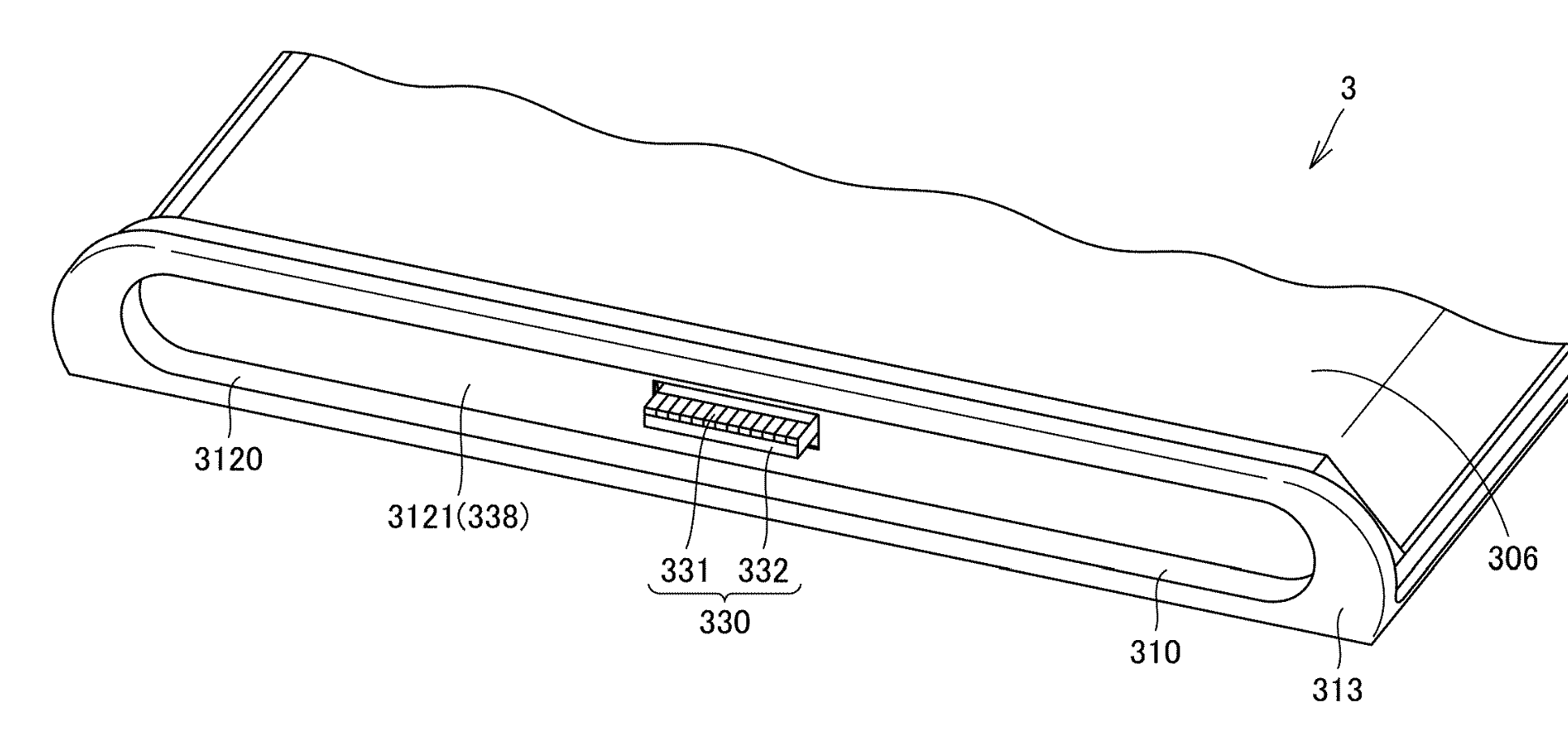
FIG.11 of US11871530B2 enlarges a narrow recessed area at the lower rear of the handheld device. A row of ribs 33 lines recess 22, and openings 32 between some of those ribs connect the exterior to the interior. Even a groove that looks like an incidental exterior detail is shaped to provide ventilation and structural support.
The patent considers several uses of this constrained space at once: where a folded stand sits, where air enters or exits, and how the console aligns when placed in a holding apparatus. The invention is less about a stand in isolation than about making a small stretch of the rear enclosure perform several jobs.
- ASSIGNEE
- Nintendo Co., Ltd.
- PRIORITY
- 2021-05-28
- PUBLISHED
- 2024-01-09
- PUBLICATION
- US11871530B2
- INVENTORS
- Junichiro Miyatake / Yuya Okazaki / Takafumi Nishida
Stacking the screen, boards, metal sheets, and fan inside one shell
What is it?
FIG.2 in US20250024631A1 is an exploded view of a handheld electronic apparatus. It separates the display panel 5 and thermally conductive sheet 25, the front housing half 20, circuit board 40, fan 60, rear metal sheet 50, battery 75, and rear housing half 30. It makes visible how much hardware must fit just behind a portable screen.
The patent's focus is on how air travels through that crowded arrangement. Heat-generating components can sit on both sides of the board, while intake air must reach the fan through confined passages. The disclosure proposes different clearances on the two sides according to the thermal load. The order of parts and the air space left between them are both engineering decisions.
- ASSIGNEE
- Nintendo Co., Ltd.
- PRIORITY
- 2023-07-11
- PUBLISHED
- 2025-01-16
- PUBLICATION
- US20250024631A1
- INVENTORS
- Takafumi Nishida / Kohei Matsumoto
How does a dock find a connector you cannot see?
What is it?
Switch 2 can switch to television play by placing the console in its dock. The earlier US11171448B2 patent addresses a common physical problem: how to guide an electronic device onto the correct charging contacts when the user cannot directly see them.
The disclosure uses multiple fitting portions, an electrical contact, and movable components that can accommodate some positional mismatch. It treats the moment of insertion as a mechanical design problem, not just a question of supplying electrical power.
- ASSIGNEE
- Nintendo Co., Ltd.
- PRIORITY
- 2015-10-27
- PUBLISHED
- 2021-11-09
- PUBLICATION
- US11171448B2
- INVENTORS
- Shinji Hirose / Daisuke Kumazaki / Takafumi Nishida
Hiding the seam where hands grip the controller
What is it?
In FIG.15 of US12246248B2, the right-hand grip 8b is shown partway detached from the main controller housing. The label “BOUNDARY PORTION” points to the junction of these pieces. The patent describes separate left and right grip members covering part of the seam between front and rear housing shells.
For someone holding a controller over a long session, the palms stay in contact with the grip surfaces. The described construction seeks to join the housing and grip surfaces smoothly and limit the uncomfortable step or seam the user might otherwise feel. Even a small boundary between molded parts can shape the experience.
- ASSIGNEE
- Nintendo Co., Ltd.
- PRIORITY
- 2016-06-10
- PUBLISHED
- 2025-03-11
- PUBLICATION
- US12246248B2
- INVENTORS
- Hitoshi Tsuchiya / Fumiyoshi Suetake / Takanori Okamura
Where does an analog stick stop when you tilt it?
What is it?
FIG.16 of US11497987B2 places an upright analog stick, shown with solid lines, beside its tilted position in dashed lines. The protruding portion 413 of the moving member 41 meets an internal pedestal 42. The figure labels the two contact points CPa and CPb and measures distances L3 and L4 from the shaft's center.
Rather than having the stick shaft rub directly against the edge of the housing opening, the mechanism limits tilt through a protrusion touching the pedestal inside. By bringing L3 and L4 close to the same value, the design aims to reduce relative sliding at these contact surfaces as the user moves the stick around its full perimeter, limiting friction-related resistance.
- ASSIGNEE
- Nintendo Co., Ltd.
- PRIORITY
- 2019-10-17
- PUBLISHED
- 2022-11-15
- PUBLICATION
- US11497987B2
- INVENTORS
- Takanori Okamura / Yuki Taniguchi / Hiroki Ikuta / Keisuke Seko / Masaya Takei
Sharing the game without sharing the program: a 2015 idea
What is it?
Nintendo Switch 2's GameShare lets a system with a supported game invite other compatible systems to join without each running its own copy. An instructive precursor is US20170095735A1, which claims priority in October 2015 and was published in April 2017.
The patent's FIG.1 describes a master apparatus running application processing and generating images, client apparatuses that receive images and send their inputs back, and separate audience devices that view the output. It is not evidence that this exact patent was implemented in GameShare. It does, however, document an earlier Nintendo concept of one machine doing the game processing while several devices share in the experience.
- ASSIGNEE
- Nintendo Co., Ltd.
- PRIORITY
- 2015-10-01
- PUBLISHED
- 2017-04-06
- PUBLICATION
- US20170095735A1
- INVENTORS
- Yoshihisa Kondo / Yuki Mizuguchi / Masayoshi Oki / Pacome Danhiez / Romain Bailly / Yann Benigot
AFTER THE FIGURES
A new machine is also a collection of older ideas
Nintendo Switch 2's portable-and-detachable architecture reaches back to a 2015 priority filing. Magnetic attachment and a mouse-capable controller introduce new ways to use that architecture.
Just as important are the inventions that remain largely invisible while playing: the shape of a stand beside ventilation openings, different air paths around a circuit board, the alignment of contacts inside a dock, and small surfaces that define how a grip or stick feels. Each tackles a physical problem in everyday use.
The final drawing introduces a related idea from 2015: one console can run the program while others receive images and send back input. Its direct patent-to-product link with GameShare remains unverified. These drawings reveal a succession of choices about how people hold, attach, cool, charge, and share experiences across consoles.
SOURCES
Primary sources
- US10583356B2 — Information processing system, information processing device, controller device and accessory
- US20260061307A1 — Game controller
- US20260061307A1 — Game controller
- US11871530B2 — Electronic device and device holding system
- US20250024631A1 — Electronic apparatus
- US11171448B2 — Charger and charging system
- US12246248B2 — Game controller
- US11497987B2 — Input device, game controller, and information processing apparatus
- US20170095735A1 — Information processing system, information processing method, information processing apparatus, and non-transitory storage medium encoded with computer readable information processing program