A light gun, a handheld screen, a floor board, a ring and a paper card ask different things of the player. Nintendo's patent drawings show how aiming, tilting, balancing, squeezing and presenting an object can each become a way to play.
Shoot a screen with a light gun to trigger the next scene
What is it?
The gun sends light toward a target area on the screen. A detected hit switches the projected scene to show the target in an altered state; the paired film projectors provide the before-and-after images.
Look at the beams drawn from the two units below the screen. The scene change is built into an optical and mechanical system, rather than being just a new image generated by a modern console.
- ASSIGNEE
- Nintendo Co., Ltd.
- PRIORITY
- 1974-09-16
- PUBLISHED
- 1976-06-01
- PUBLICATION
- US3960380A
- INVENTORS
- Gunpei Yokoi
Control a handheld game by tilting the device itself
What is it?
The cartridge entering the top of the machine matters. In the main embodiment, it houses an acceleration sensor, so moving or tilting the assembled handheld can change the game image. The document also allows the sensor to be built into the main body.
The axis diagram supplies a frame for describing movement; it is not a picture of three sensors inside the screen. Buttons remain available while movement adds another kind of input.
- ASSIGNEE
- Nintendo Co., Ltd.
- PRIORITY
- 1999-10-04
- PUBLISHED
- 2003-11-04
- PUBLICATION
- US6641482B2
- INVENTORS
- Iwao Masuyama / Toshiaki Suzuki
Stand on a board and use weight shifts as controller input
What is it?
The dotted circles near the corners mark load sensors beneath the supporting surface. Their readings can be combined or compared to give game software information about how the player distributes weight.
The second drawing changes the meaning of the first: the board is an input device in front of a game screen. Shifting weight changes the values supplied to the game, even though the player holds nothing.
- ASSIGNEE
- Nintendo Co., Ltd.
- PRIORITY
- 2007-04-20
- PUBLISHED
- 2013-11-05
- PUBLICATION
- US8574080B2
- INVENTORS
- Hitoshi Yamazaki / Takao Sawano / Tadashi Sugiyama
Insert the controller into a steering wheel
What is it?
The central recess receives a game controller. The surrounding rim gives the player a steering-wheel grip, while movable parts let fingers operate buttons on the controller inside.
Read the empty attachment beside the use drawing: the accessory changes where the hands sit and how they reach the controls. The electronic controller and its physical handle do different jobs.
- ASSIGNEE
- Nintendo Co., Ltd.
- PRIORITY
- 2017-01-11
- PUBLISHED
- 2018-02-20
- PUBLICATION
- US9895606B1
- INVENTORS
- Hideaki Kamata / Yuriko Sakai
Push and pull a ring to control a game
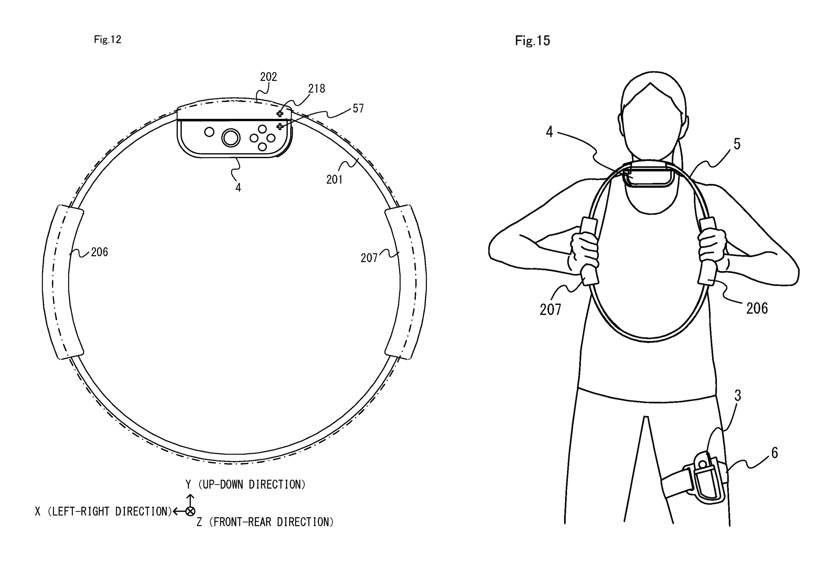
What is it?
The ring is intended to deform when its grips are pushed together or pulled apart. The patent describes a strain detector that converts this deformation into a signal for game input.
The attached controller sits above the two grips, leaving the hands on the elastic structure. The use drawing also includes a separate controller on the thigh, combining upper-body input with leg movement.
- ASSIGNEE
- Nintendo Co., Ltd.
- PRIORITY
- 2019-06-20
- PUBLISHED
- 2020-08-25
- PUBLICATION
- US10751613B1
- INVENTORS
- Yoshitaka Tamura / Yoshiyasu Ogasawara / Tomofumi Ikeda / Yuko Zenri
Make the game controller itself a sphere
What is it?
The controller groups its controls around a rounded housing that fits in one hand. The use drawing makes the arrangement legible: the thumb works the forward joystick while the other fingers wrap around the ball.
The band around the housing is also discussed as an orientation cue. A sphere has no obvious front by itself, so visible seams and the placement of controls help give it a usable direction.
- ASSIGNEE
- Nintendo Co., Ltd.
- PRIORITY
- 2018-05-25
- PUBLISHED
- 2019-11-28
- PUBLICATION
- US20190358533A1
- INVENTORS
- Masaya Takei / Shinta Minagawa / Kazuhiro Maruyama / Kohei Odanaka
Hold up a paper card to exchange data with a game
What is it?
The lower display area contains the antenna used for contactless communication. Holding the card there lets the device exchange information with an IC chip and antenna embedded in the card.
The card remains a printed collectible, but its stored data can also connect it to the game. The patent describes both character-related data and a writable region for information supplied by the game device.
- ASSIGNEE
- Nintendo Co., Ltd.
- PRIORITY
- 2015-04-01
- PUBLISHED
- 2019-05-07
- PUBLICATION
- US10279273B2
- INVENTORS
- Satoshi Kawanabe / Kenko Kawahara / Hideaki Kamata / Norio Asakura
Steer a vehicle with 'two mice,' one in each hand
What is it?
The left panel shows one mouse in each hand moving along a work surface. The right panel shows the virtual object those movements control, with separate wheels on its left and right sides.
The publication derives left and right velocity parameters from the respective mouse movements. Their combination determines travel, while a difference between them changes the direction of the virtual object.
- ASSIGNEE
- Nintendo Co., Ltd.
- PRIORITY
- 2023-11-16
- PUBLISHED
- 2025-11-27
- PUBLICATION
- US20250360404A1
- INVENTORS
- Hiroki Hamaue / Yoshinori Konishi / Taro Nonaka
Strap a controller to your leg and use foot movement as input
What is it?
A pocket receives the controller, and the belt threads through the opening beside it before fastening around the leg. The two drawings explain both the flat fabric accessory and the way it holds the electronics in place.
With the controller attached to the body, its motion sensors can supply leg-movement information. The same family also shows this belt used alongside the ring, as seen in article FIG. 05.
- ASSIGNEE
- Nintendo Co., Ltd.
- PRIORITY
- 2019-06-20
- PUBLISHED
- 2022-03-01
- PUBLICATION
- US11260293B2
- INVENTORS
- Yoshitaka Tamura / Yoshiyasu Ogasawara / Tomofumi Ikeda / Yuko Zenri
Turn a ceiling-like projection surface into the game screen
What is it?
The person lies below the ceiling while the projector sits off to one side. The marked lines distinguish the projection direction, the viewer position and the geometry of the surface above them.
The system measures the projection surface and adjusts the image to reduce geometric distortion as viewed by the user. The document includes controller-driven rotation and correction, rather than assuming that the projector faces a conventional upright screen.
- ASSIGNEE
- Nintendo Co., Ltd. / MegaChips Corporation
- PRIORITY
- 2015-03-30
- PUBLISHED
- 2018-03-27
- PUBLICATION
- US9928580B2
- INVENTORS
- Motoyasu Tanaka / Yuki Haraguchi / Fumiya Shingu / Eizi Kawai / Kazuhiro Hosoi
AFTER THE FIGURES
More ways to act, not simply more buttons
Across these drawings, the useful comparison is what the player does. Aim at a screen, tilt the screen itself, shift weight, turn a wheel, deform a ring, cradle a ball, present a card, coordinate two hands or move a leg: each action offers the game a different signal.
The accessories also show several ways to get there. A wheel reshapes the grip around electronics, a belt moves them onto the body, and a ring adds a deformable sensing structure. The final projection system extends the same question to the room where the image appears.
These documents preserve choices about the relationship between bodies, objects and software. Their value is in making those choices visible, whether or not a particular proposal reached a product.
SOURCES
Primary sources
- US3960380A — Light ray gun and target changing projectors
- US6641482B2 — Portable game apparatus with acceleration sensor and information storage medium storing a game program
- US8574080B2 — Game controller, storage medium storing game program, and game apparatus
- US9895606B1 — Accessory device
- US10751613B1 — Apparatus and method
- US20190358533A1 — Game controller
- US10279273B2 — Trading card and trading card set
- US20250360404A1 — Non-transitory computer-readable storage medium having game program stored therein, game processing method, and system
- US11260293B2 — Method and apparatus with deformable body engaging portion and game controller attachment portion
- US9928580B2 — Projection system, projector apparatus, and projection method