Microsoft interfaces are easy to picture as familiar objects: a Windows screen, a keyboard and mouse, or an Xbox controller. Put the company's patent FIGs side by side, however, and those objects begin to dissolve into the body and the room. A ring reads finger flexion. Forearm muscles become input signals. A glove changes the viscosity of fluid inside it.
The output side does not stay fixed either. A keyboard appears in a holographic scene. Presentation data spreads across walls and furniture. Tiny robots race beneath a hand to give a virtual object a real contact surface. Controller parts become replaceable, a backpack watches the environment while advising a skier, and a near-eye display is decomposed into an array of projectors and a waveguide.
These mechanisms are proposals described in US patent publications assigned to Microsoft Corp or Microsoft Technology Licensing. A one-to-one link between each patent and a public product remains unverified.
Turn the bend of a finger into an input with a ring
What is it?
"Smart ring" places sensing in a ring so signals corresponding to flexion and rotation of the wearing finger can be detected. FIG. 1 lines up several poses of the same ring-equipped finger with changes on tablet 112.
The patent also considers combining finger pose with contact against other fingers or objects. Instead of adding more touch targets to a screen, it adds the shape of the hand outside the screen to the vocabulary of input.
- ASSIGNEE
- Microsoft Technology Licensing LLC
- PRIORITY
- 2014-09-17
- PUBLISHED
- 2016-03-17
- PUBLICATION
- US20160077587A1
- INVENTORS
- Wolf Kienzle / Kenneth P. Hinckley
Recognize hand gestures from the electrical signals in the forearm
What is it?
"Recognizing gestures from forearm EMG signals" samples electromyographic signals from multiple electrodes around the forearm and uses machine learning to recognize hand and finger gestures. FIG. 1 shows sensor array 102 arranged around forearm band 100.
When a finger moves, the muscle activity that produces the movement is already present in the arm. By learning those signal patterns, the system can classify finger movement or hand pose without requiring the hand to remain inside a camera's field of view.
- ASSIGNEE
- Microsoft Technology Licensing LLC
- PRIORITY
- 2008-06-26
- PUBLISHED
- 2009-12-31
- PUBLICATION
- US20090327171A1
- INVENTORS
- Desney Tan / Dan Morris / Scott Saponas / Ravin Balakrishnan
Stiffen fluid inside a glove to push back against the hand
What is it?
"Haptic feedback system" puts a fluid with adjustable viscosity inside fluidic channels of a wearable and changes that viscosity by varying a field. FIG. 1 shows an HMD user wearing the system on the hands while interacting with a ball-shaped object.
When the fluid moves easily, the hand can bend more freely. Increasing viscosity can increase resistance to deformation. A virtual hard object can therefore be represented not only by a buzz but by making the real glove more difficult to move through.
- ASSIGNEE
- Microsoft Technology Licensing LLC
- PRIORITY
- 2017-06-30
- PUBLISHED
- 2019-01-03
- PUBLICATION
- US20190004602A1
- INVENTORS
- James David Holbery
Type on a holographic keyboard while your real hand hangs at your side
What is it?
"Holographic keyboard display" receives depth information about a real hand, displays a holographic hand representing it, and adaptively places a keyboard hologram at a virtual distance below that hand. In FIG. 3, the user's actual right hand hangs at the side while the displayed hand image sits over the keyboard.
The virtual keyboard does not have to remain literally attached to the physical location of the hand. If the user shifts posture or the hand drifts, the system can preserve a usable hand-to-keyboard relationship in the holographic environment.
- ASSIGNEE
- Microsoft Technology Licensing LLC
- PRIORITY
- 2014-07-15
- PUBLISHED
- 2016-01-21
- PUBLICATION
- US20160018985A1
- INVENTORS
- Rotem Bennet / Lewey Geselowitz / Wei Zhang / Adam G. Poulos / John Bevis / Kim Pascal Pimmel / Nicholas Gervase Fajt
Spread a presentation across walls, shelves and the room itself
What is it?
"Presenting augmented reality display data in physical presentation environments" builds a configuration describing locations in a physical presentation space and maps augmented-reality objects to those locations. FIG. 3 distributes numbers, charts and other content across walls, shelving and furniture.
The result is not merely one enormous virtual rectangle. Room geometry, available locations, previous layouts and preferences can participate in deciding where different pieces of information appear. Presentation layout expands from the slide into the physical environment.
- ASSIGNEE
- Microsoft Technology Licensing LLC
- PRIORITY
- 2017-06-30
- PUBLISHED
- 2019-01-03
- PUBLICATION
- US20190005724A1
- INVENTORS
- Michel Pahud / Nathalie Riche / Eyal Ofek / Christophe Hurter / Steven Mark Drucker
Drive tiny robots under your hand so virtual objects become touchable
What is it?
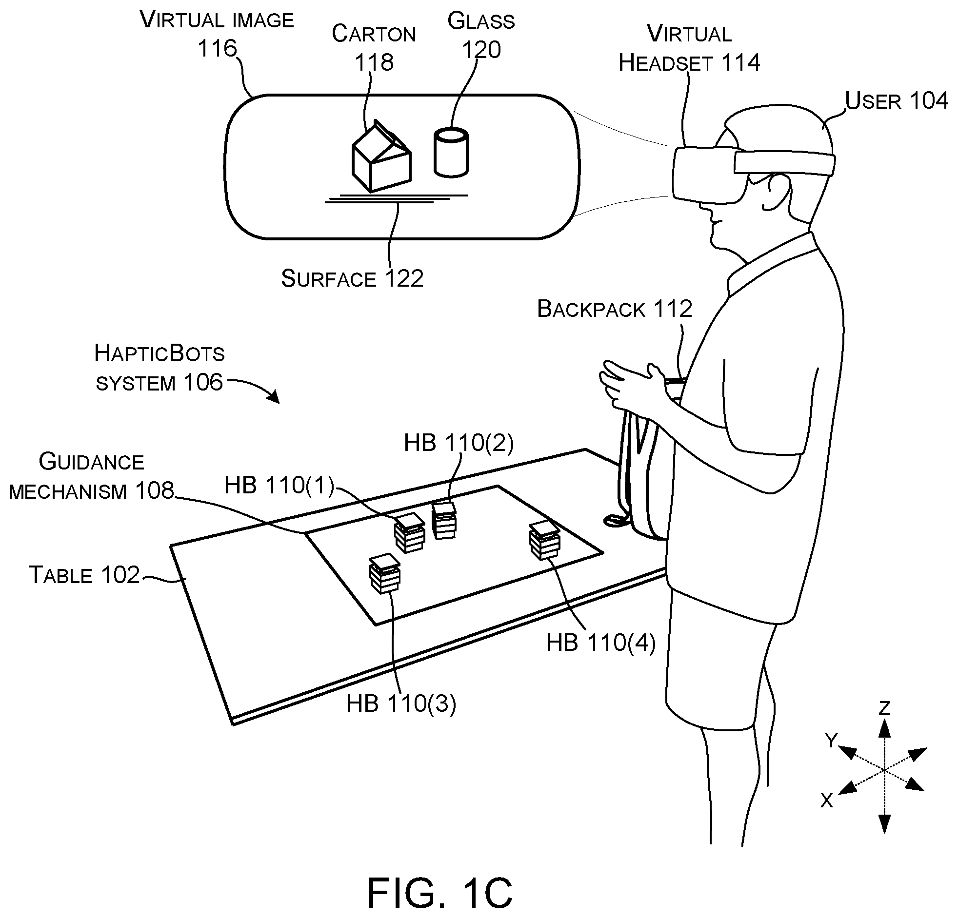
"Mobile Haptic Robots" describes multiple small HapticBots that move across a surface to provide physical haptic representations of virtual objects. In FIG. 1C, several HapticBots occupy table 102 while the user's virtual view contains a carton and a glass.
The robots can move to needed locations, and embodiments can also adjust properties such as the height or pitch of an upper surface. If a bot arrives beneath the place where a virtual box is supposed to be, a hand reaching into empty graphics can encounter a real surface.
- ASSIGNEE
- Microsoft Technology Licensing LLC
- PRIORITY
- 2021-06-24
- PUBLISHED
- 2022-12-29
- PUBLICATION
- US20220409996A1
- INVENTORS
- Mar Gonzalez Franco / Eyal Ofek / Michael Jack Sinclair / Ryo Suzuki
Swap game-controller buttons with magnets
What is it?
"Game controller with removable magnetic button" uses magnetic attraction between a button-retention feature in the controller and a selected button accessory. FIG. 1 shows the basic controller layout with its multiple physical controls.
The idea goes beyond remapping a command in software. Differently shaped accessories can be attached over the input hardware, changing the physical part that the finger actually touches to suit a game or preference.
- ASSIGNEE
- Microsoft Technology Licensing LLC
- PRIORITY
- 2015-06-09
- PUBLISHED
- 2016-12-15
- PUBLICATION
- US20160361635A1
- INVENTORS
- Aaron Schmitz
Let a backpack look around and tell a skier that the route is out of bounds
What is it?
"Artificial intelligence assisted wearable" describes a wearable such as a backpack with sensors including microphones and cameras. In FIG. 3B, a skier asks about a direction and the backpack replies that it is out of bounds and suggests skiing to the right.
The point is that the spoken command does not need to identify every object explicitly. References such as this, that or over there can be interpreted together with what the sensors see in the environment. The digital assistant becomes equipment that shares the user's context.
- ASSIGNEE
- Microsoft Technology Licensing LLC
- PRIORITY
- 2019-09-13
- PUBLISHED
- 2021-03-18
- PUBLICATION
- US20210081749A1
- INVENTORS
- Brian Stephen Claire
Build a near-eye image from a row of projectors instead of one screen
What is it?
"Near-eye display systems utilizing an array of projectors" arranges multiple projectors and directs their image light toward an input coupler in a waveguide. FIG. 1 shows signals moving from controller 100 to projector array 102 and light propagating through waveguide 108 toward eye 120.
Rather than treating the display as one panel, the design splits it into an array of small light sources and an optical path that expands the exit pupil. The screen becomes less of an object and more of a controlled route for image light directly in front of the eye.
- ASSIGNEE
- Microsoft Technology Licensing LLC
- PRIORITY
- 2022-09-14
- PUBLISHED
- 2024-03-14
- PUBLICATION
- US20240085714A1
- INVENTORS
- Joel Steven Kollin / Andreas Georgiou / Ishan Chatterjee / Bernard Charles Kress / Maria Esther Pace / Mario Possiwan
Fold one continuous display across the hinge
What is it?
"Flexible display overcenter assembly" describes a foldable electronic device whose flexible display spans two housing parts. FIG. 1 shows the device open, moving through the fold and closed, with the same display surface continuing across the hinge region.
The mechanical problem is to avoid forcing a fragile flexible display into a damaging sharp crease. Flanges and hinge assemblies form and support a radius for the display in the closed position, pursuing both a compact carried device and a larger continuous viewing surface.
- ASSIGNEE
- Microsoft Technology Licensing LLC
- PRIORITY
- 2011-06-03
- PUBLISHED
- 2012-12-06
- PUBLICATION
- US20120307472A1
- INVENTORS
- David D. Bohn / Paul M. O'Brien / Christopher B. Fruhauf
AFTER THE FIGURES
In these Microsoft patents, input devices and screens stop being fixed objects
Across the ten drawings, finger posture, electrical activity in muscle, resistance inside a glove, a wall in the room and robots moving across a tabletop can each temporarily take on the job of input or output.
An AI backpack makes the computer observe the surrounding world, while a foldable display makes the hardware itself change shape. Each invention redraws the boundary between person, object, room and optical system in a different place.
In this version of Microsoft's strange future, the roles of mouse, keyboard, screen and controller extend beyond permanent, dedicated hardware. When input is needed, it can be read from the body. When a display is needed, it can be placed into space. When touch is needed, a robot can drive underneath the hand. The interface becomes something assembled for the moment.
SOURCES
Primary sources
- US20160077587A1 — Smart ring
- US20090327171A1 — Recognizing gestures from forearm EMG signals
- US20190004602A1 — Haptic feedback system
- US20160018985A1 — Holographic keyboard display
- US20190005724A1 — Presenting augmented reality display data in physical presentation environments
- US20220409996A1 — Mobile Haptic Robots
- US20160361635A1 — Game controller with removable magnetic button
- US20210081749A1 — Artificial intelligence assisted wearable
- US20240085714A1 — Near-eye display systems utilizing an array of projectors
- US20120307472A1 — Flexible display overcenter assembly